Mark the bottom and inside face of both cabinet sides before laying out shelf pin holes. Every row needs the same height reference. A row measured from the top on one side and from the bottom on the other can look orderly while leaving the shelf tilted.
Choose the pins and drilling guide together. Hole diameter, hole depth and distance from the panel edge are separate dimensions. A guide with the correct spacing can still make the wrong diameter hole for your pins. Check the actual pin fit on scrap from the cabinet sides before drilling a finished panel.
Choose the usable adjustment zone
Start with the items the cabinet will hold. Put a tall item beside the drawing and allow space to lift it off the shelf. Decide the lowest and highest useful support positions. There is little reason to drill behind a fixed divider, a drawer or hardware that prevents a shelf from occupying that position.
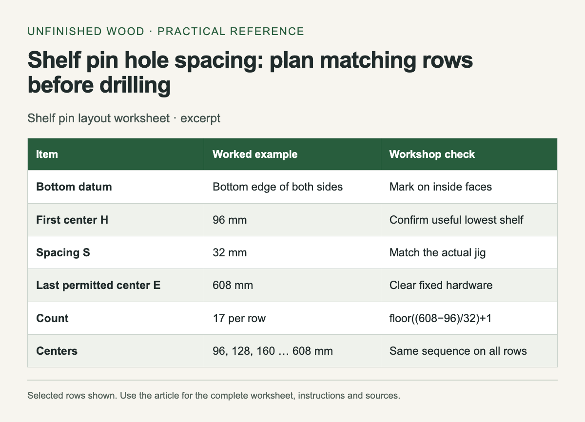
Keep the first hole at a documented distance above the bottom reference. Call this height H. With spacing S, the following holes are H + S, H + 2S and so on. For a usable zone ending at E, the number of holes is floor((E − H) ÷ S) + 1, provided E is at least H. The last hole may fall below E; that is expected.
For example, a first center 96 mm above the bottom, a final allowed center of 608 mm and 32 mm spacing produce 17 holes. Their centers run from 96 to 608 mm. If the upper limit were 600 mm, there would be 16 holes and the final center would be 576 mm. This count includes both endpoints only when the interval divides exactly.
Keep spacing and setback separate
Kreg's current 5 mm shelf pin jig specifies 32 mm hole spacing and a 37 mm contact-edge position. Other guides and older versions use other setbacks. Read your own guide's instructions rather than treating a familiar number as universal.
Front and back rows must support the same shelf at the same height. They also need to clear hinges, backs and other hardware. Lay the hardware on the drawing, including the space it occupies when moving. A pin hidden behind an open hinge arm is not a usable shelf position.
Prove the layout on scrap
Clamp a test strip securely, set the depth stop as instructed and drill a few holes. Measure the hole center positions and try the pins. If the drill has a projecting center point, include that point when checking how much panel thickness remains. Inspect the reverse face under light; a tiny puncture can be easy to miss.
Place the cabinet sides inside face up and label them left and right. Copy the bottom datum to both. After drilling the first few holes, support a straight scrap shelf on matching pins to check the relationship before completing long rows. Record the guide orientation on the worksheet, especially if a reversible fence changes the reference edge.
The worksheet controls location only. Shelf span, material, pin capacity, cabinet anchoring and the weight of stored items still need their own design checks. Save the layout with the cabinet dimensions so replacement shelves can use the same support system.
For several matching cabinets, transfer the layout with a story stick so repeated measurements begin from the same reference edge.
| Item | Worked example | Workshop check |
|---|---|---|
| Bottom datum | Bottom edge of both sides | Mark on inside faces |
| First center H | 96 mm | Confirm useful lowest shelf |
| Spacing S | 32 mm | Match the actual jig |
| Last permitted center E | 608 mm | Clear fixed hardware |
| Count | 17 per row | floor((608−96)/32)+1 |
| Centers | 96, 128, 160 … 608 mm | Same sequence on all rows |
| Diameter / depth | Fill from pin and jig instructions | Test the reverse face |
Related workshop guides
- Build a Simple Bookcase: Work Out the Openings Before Cutting
- Make a story stick for a project with repeated dimensions
Sources
Comments
Post a Comment